OpenMPTCProuter is an open source project which aimed to aggregate multiple internet connections into a single one which results higher bandwidth, failover, security and latency optimization. It uses MPTCP under the hood. So if you have multiple internet connections (Fiber, ADSL, VDSL, 3G, 4G, 5G…) which you are currently using only for load balancing or failover purpose, you can now bond those connections and get maximum throughput.
You can setup OpenMPTCProuter in various devices. In this tutorial I will show you how to setup it in Raspberry Pi 4B (RPI4). I will also use a managed switch (TL-SG108E) for VLAN functionality. The primary purpose of using VLAN is to reduce wiring and utlize single network interface of RPI4.
If you want to follow this tutorial, you need following things:
- Raspberry Pi 4 (2GB RAM will suffice)
- Any
managedswitch. I will use TL-SG108E - KVM VPS (Debian 10. At least 1 GB RAM & 1 vCPU). Choose any provider listed here. Make sure the location is closest to you and doesn’t have any transfer limitation
- At least 2 internet connections for aggregate. In my case, I will aggregate two ISP
- Access point (AP) or router
- Wiring done by at least CAT-5e/Cat-6 cables
That’s it, we don’t need any ethernet adapters for our Raspberry PI 4. We will use VLAN in our switch for sending different traffics to PI’s physical network interface.
Here how our setup will look like at the end
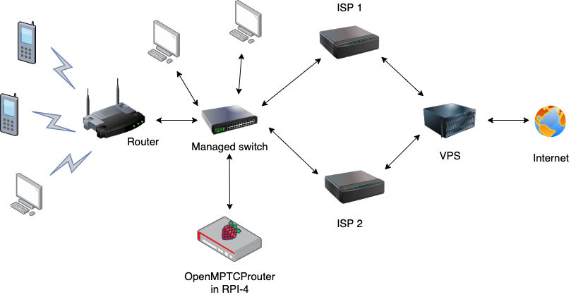 Maybe I threw you off a bit but don’t worry, I will explain what is going on in above picture along the way. One of the most important component here is switch. All the end devices are point to the switch. I don’t know why but the setup reminds me this meme. Lol

Anyway, back to the game. Let’s begin
Setup VPS
First, we will setup VPS. Aggregation/bonding will happen in VPS side. Follow this guide for setting up VPS for OpenMPTCProuter. The script will do all the heavy lifting for you so don’t worry. The script is meant to be run as root in a clean VPS (no 3rd party packages are installed). Also reboot when done. You will find some keys after installation in
/root/openmptcprouter_config.txt file. Note down the keys. We need those later.
Setup OpenMPTCProuter in Rpi4
Head over to the official OpenMPTCProuter site and download ext4 image (openmptcprouter——rpi4-sysupgrade.img.gz) for Raspberry PI 4B. Download Raspberry Pi Imager or balenaEtcher to flash the ext4 image in microSD card. Put the card into Rpi4.
part 1 – setup switch
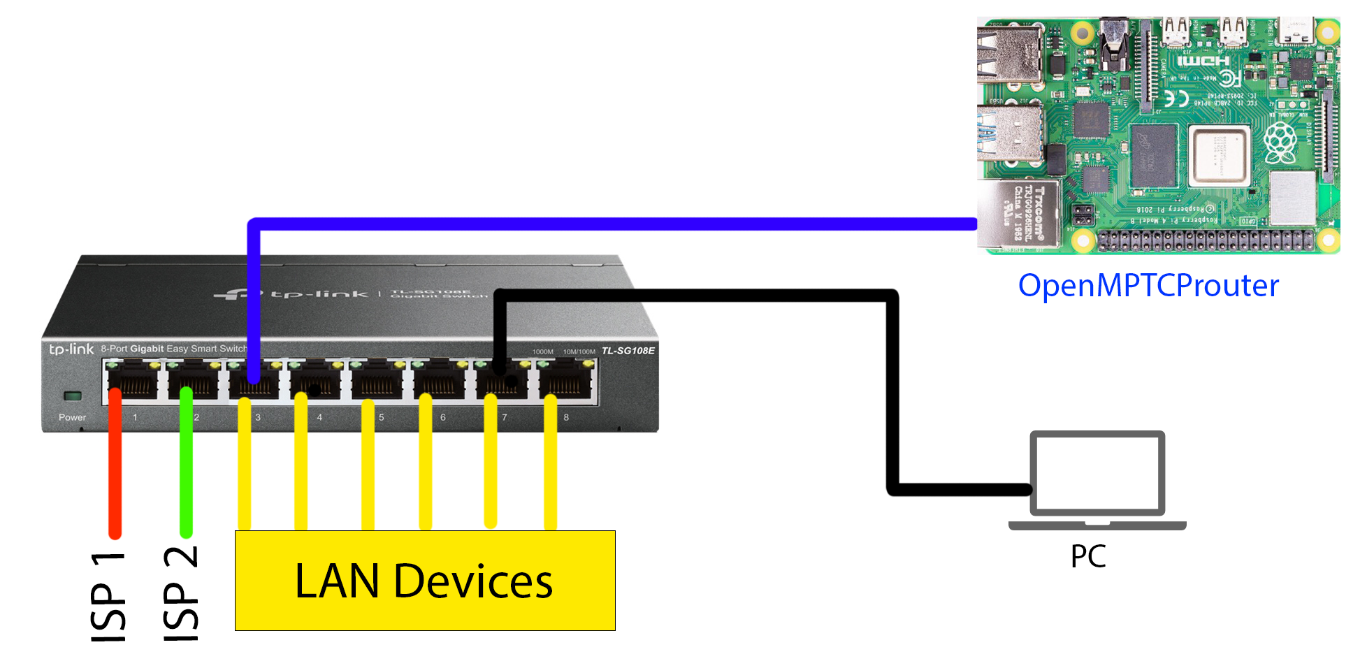
Now we will setup switch. Mostly we will setup VLAN. Since I am using TP-Link TL-SG108E (v6.6), there are 8 gigabit ports. I will use port 1 & 2 for wan connections (ISP 1 & ISP 2) and port 3 to 8 for LAN devices.
Connections:
First, connect the switch as below diagram
- ISP 1 cable to port 1
- ISP 2 cable to port 2
- A cable from RPI4’s physical interface to port 3
- A cable from your PC to port 7 (or any port from 4 to 8)
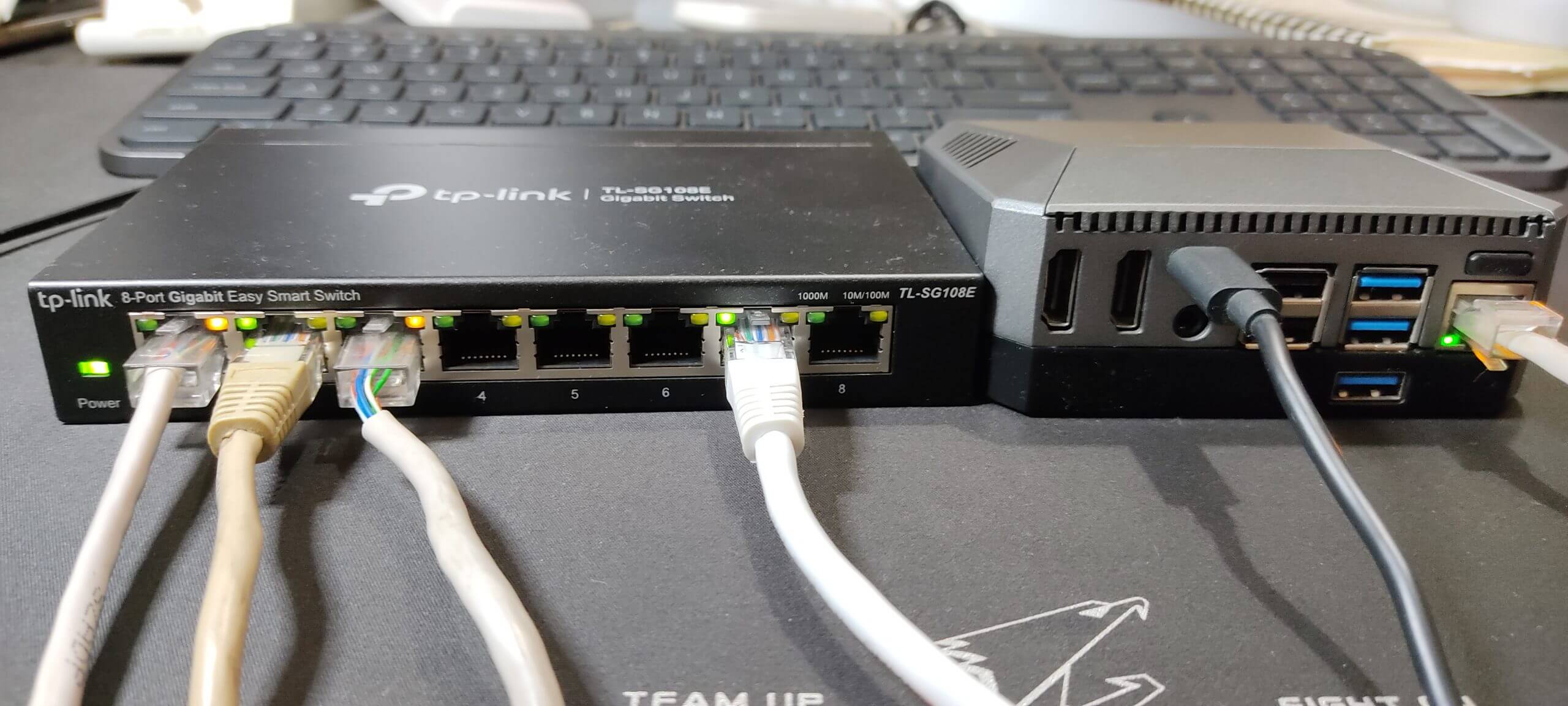
It looks like this in my side. Note: my RPI4 is enclosed with Argon ONE M.2 case so it looks different 😀
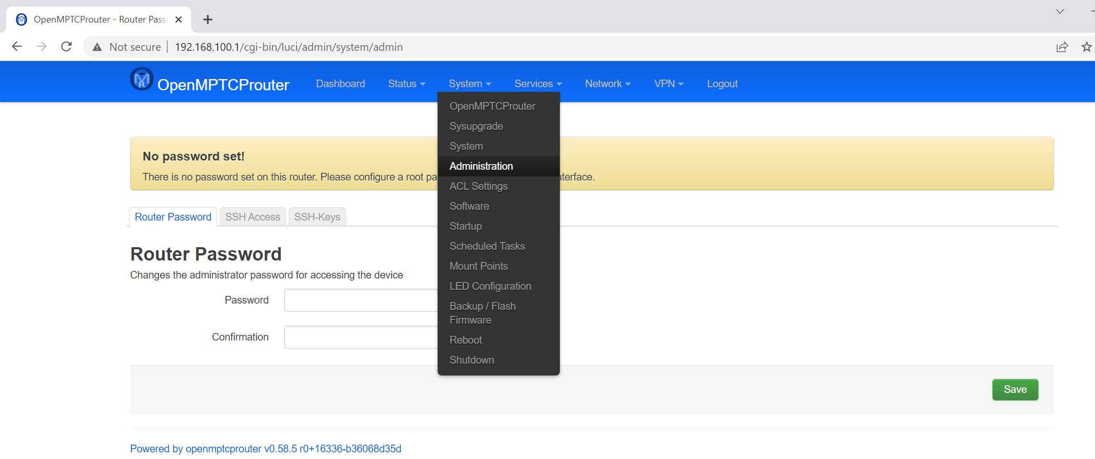
Now power up both switch and RPI4, wait a minute. Now visit the following url from your PC: http://192.168.100.1 You should see a login page
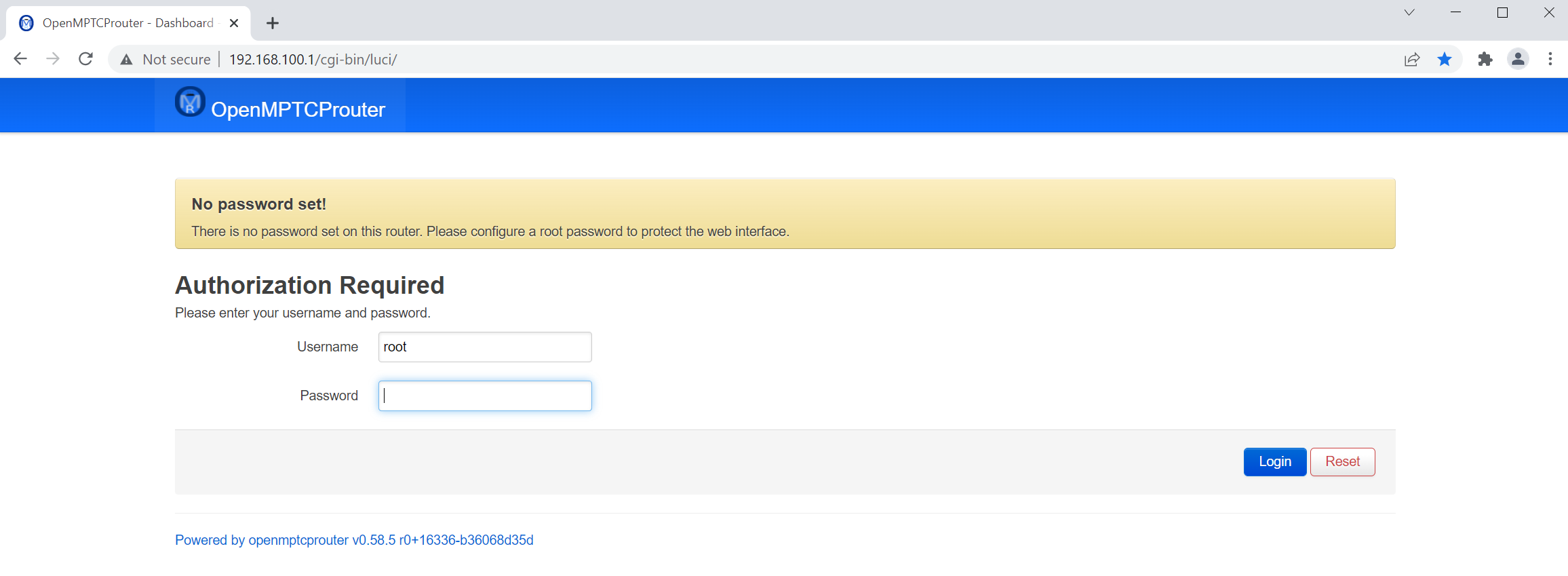
There is no password set at the beginning. Simply click login. Next, go to System > Administration and set a password and click save.
Now go to Status > Overview page. Here you should see your switch IP address.
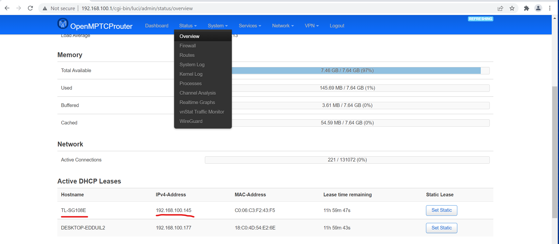
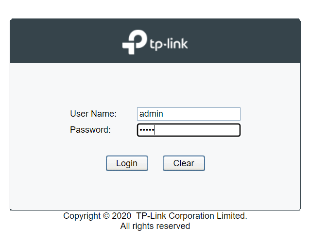
Visit that address and login to your switch. For me, the default password is admin.
Now go to VLAN > 802.1Q VLAN. Enable the configuration and click Apply
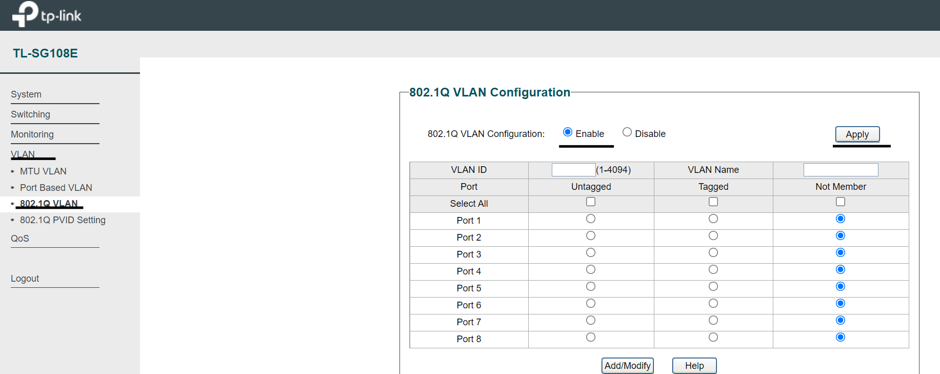
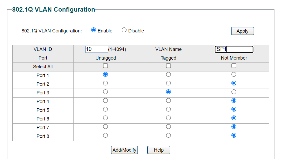
Next we need to configure the VLAN. Put VLAN ID 10, VLAN Name set to ISP1 (or any name). Since I will use port 1 for ISP1, so untagged port 1 and tagged port 3. Click Add/Modify. So for VLAN ID 10, the result will look like this:
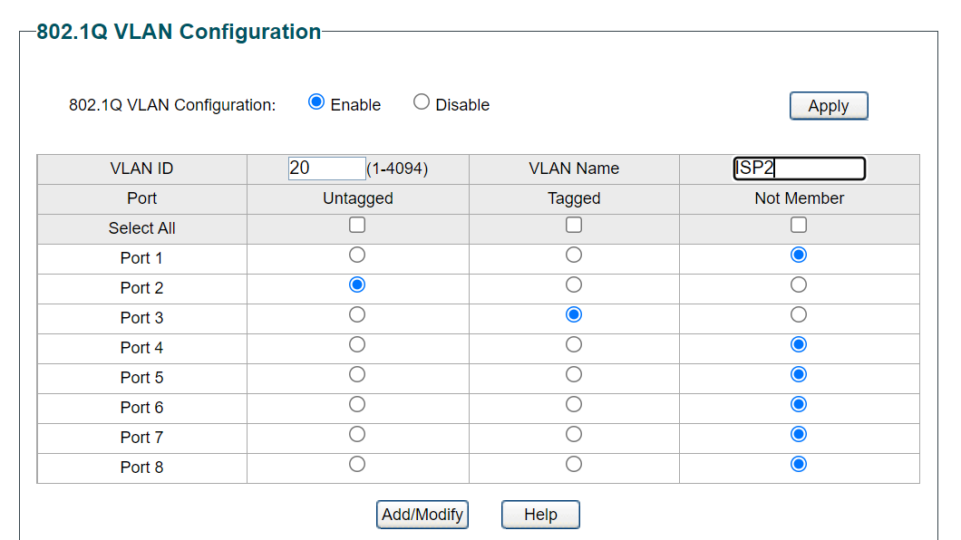
We configured port 1 & port 3 in way that they are in same (V)LAN. We will do similar configuration for ISP2. So I put 20 as VLAN ID for ISP2, name can be ISP2 or anything. Next again, untagged port 2 and tagged port 3. Click Add/Modify. So here how it looks like
Here, traffic from port 2 will pass to port 3. So port 3 now getting traffic from both port 1 and port 2. Got the picture? Great! Let’s move on.
Now we need to setup VLAN for LAN devices. So put 1 as VLAN ID, name it anything and keep port 1 and 2 not member and port 3 to 8 untagged.
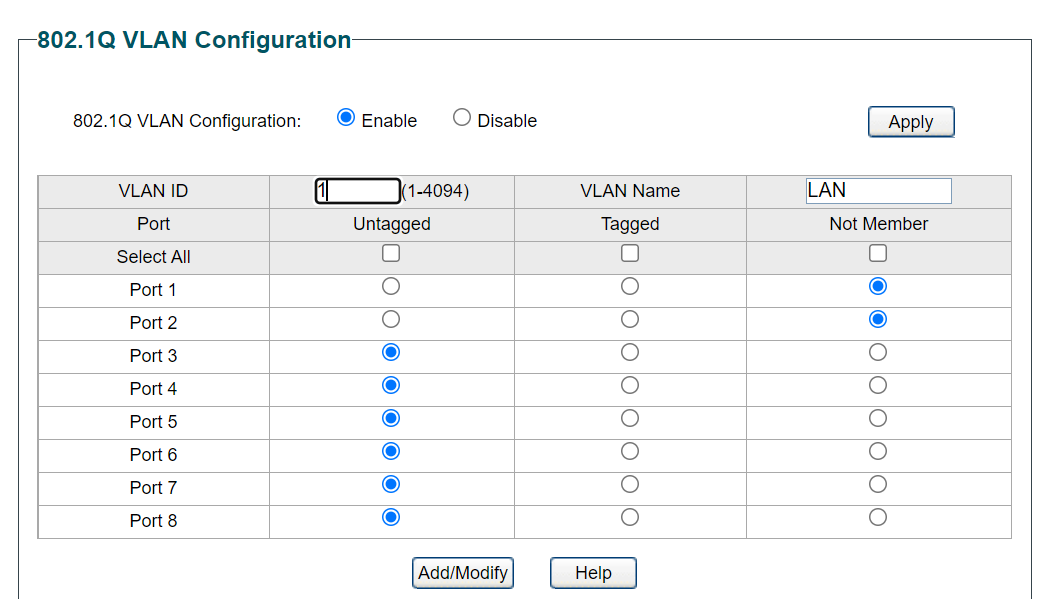
Since port 3 have traffic for both ISP1 and ISP2, we untagged/merge other ports with it. Now port 3 can share traffic with others. Make sense? Nice! Here is the final result
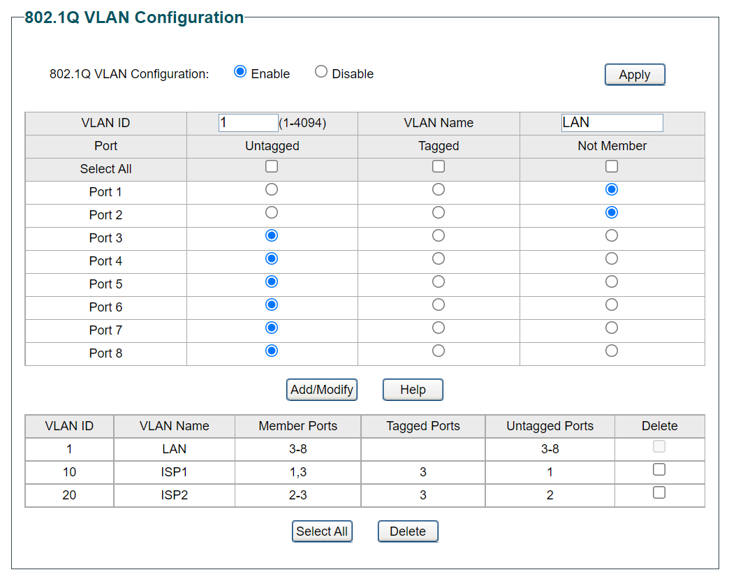
So to recap:
- port 1 –> VLAN 10 (For ISP1)
- port 2 –> VLAN 20 (For ISP2)
- port 3-8 –> VLAN 1 (For LAN devices)
NOTE: For some switches, port 1 & 2 needs to be tagged instead of untagged. In TL-SG108E (v6.6) switch, I had to untagged port 1 & 2 in order to make things work. For you mileage may vary. So play around with tagged and untagged and see which one works for you.
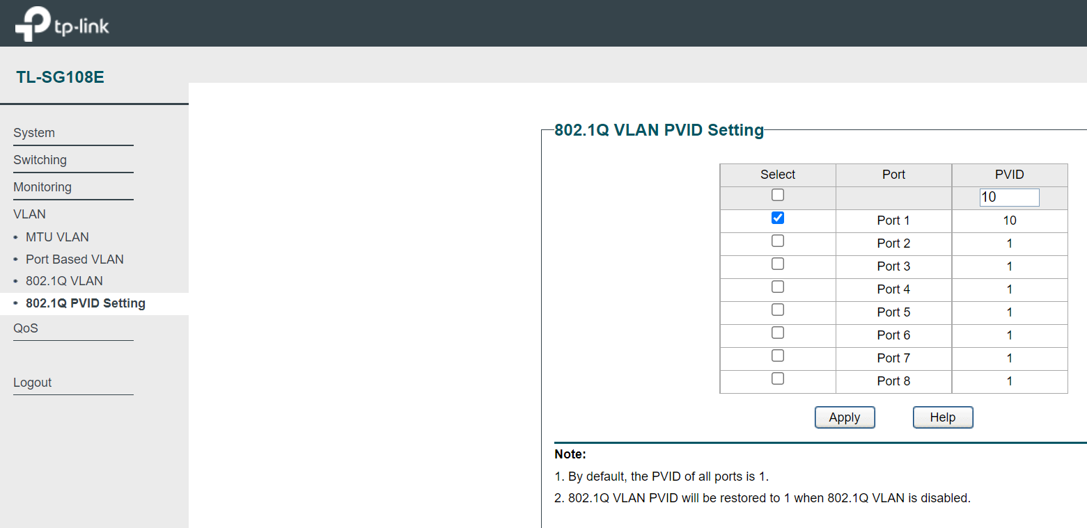
Let’s move on to next setup. Go to VLAN > 802.1Q PVID Setting, put 10 in PVID field and select port 1. Click Apply.
Similarly, put 20 as PVID, select port 2 and click Apply.
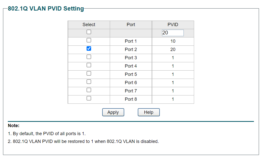
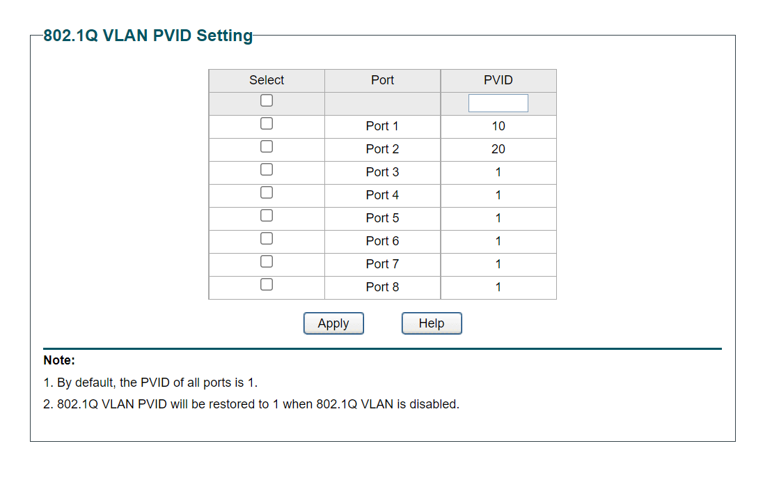
Here is our final result. Port 1 & 2 can now be identified with ID 10 & 20 respectively.
That concludes switch setup. However we are not done yet 😀 Le’ts take a short coffee break and move on to the next part 😀
part 2 – setup interfaces in router
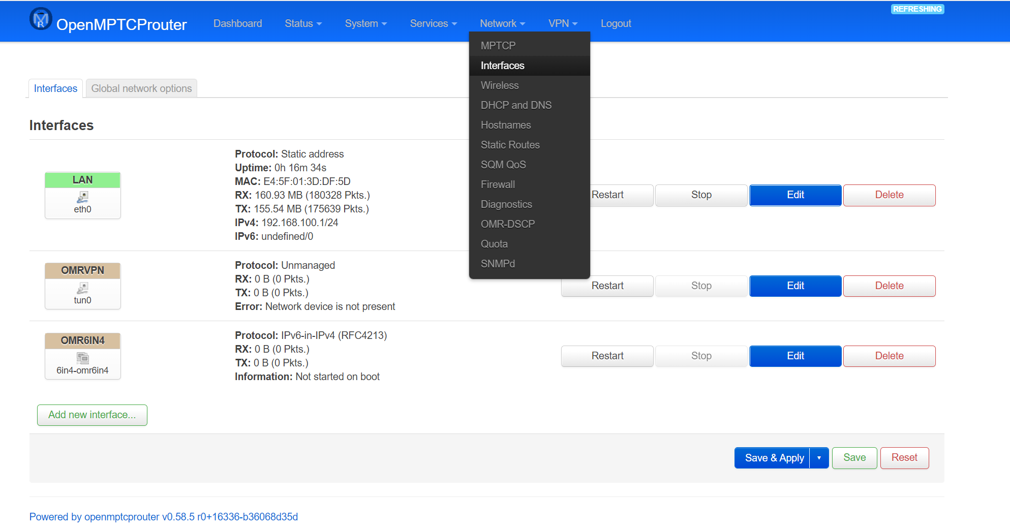
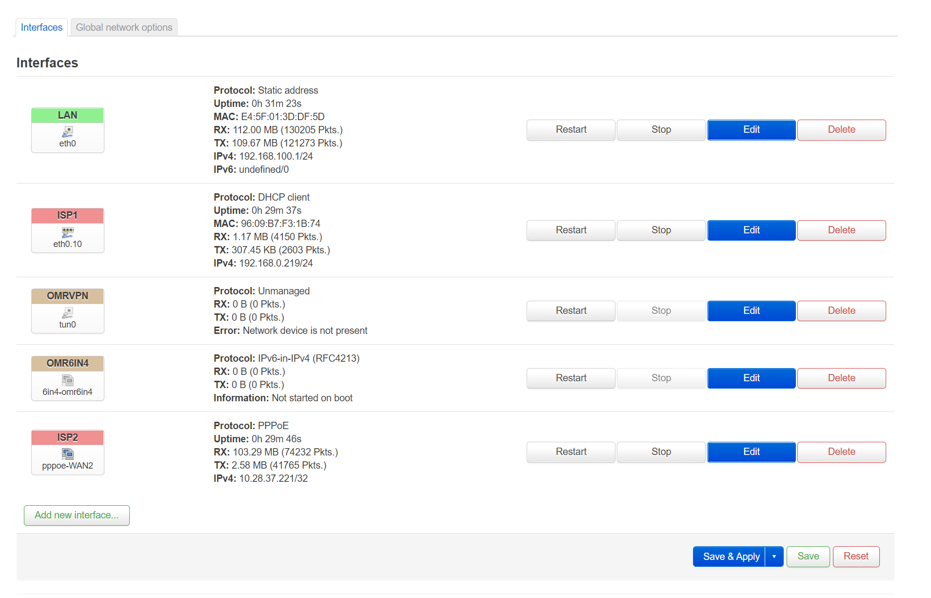
Previously, we logged in to router, So open the router tab again and navigate to Network > Interfaces. Delete default WAN1 and WAN2 interfaces. Leave LAN, OMRVPN & OMR6IN4 as it is. Save & Apply.
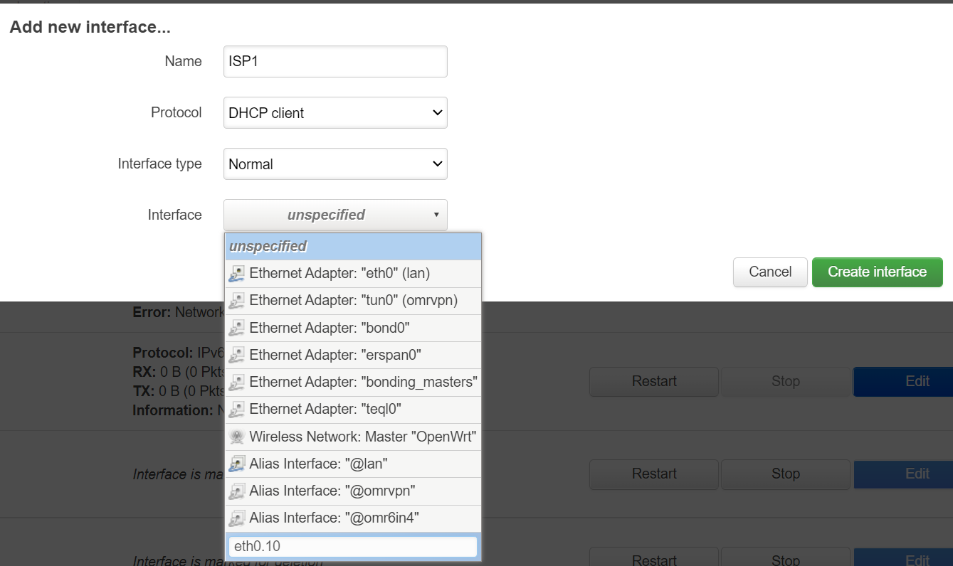
Click Add new Interface. Name anything you like. Set correct protocol. For my ISP1, it is DHCP. Next set interface type as normal. As for interface, type eth0.10. Let’s break it down why it is eth0.10.
eth0 is the physical interface of RPI4. We set VLAN ID 10 in our switch for port 1. Now in order to access port 1 from RPI4, we need to type eth0.10. Here 10 is…yeah you guessed it right, VLAN ID. That’s how we can access port 1 in switch from router.
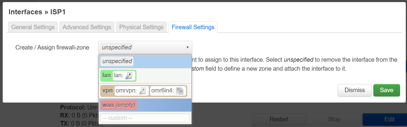
Click create interface. Make sure to add this interface in wan firewall. Click save.
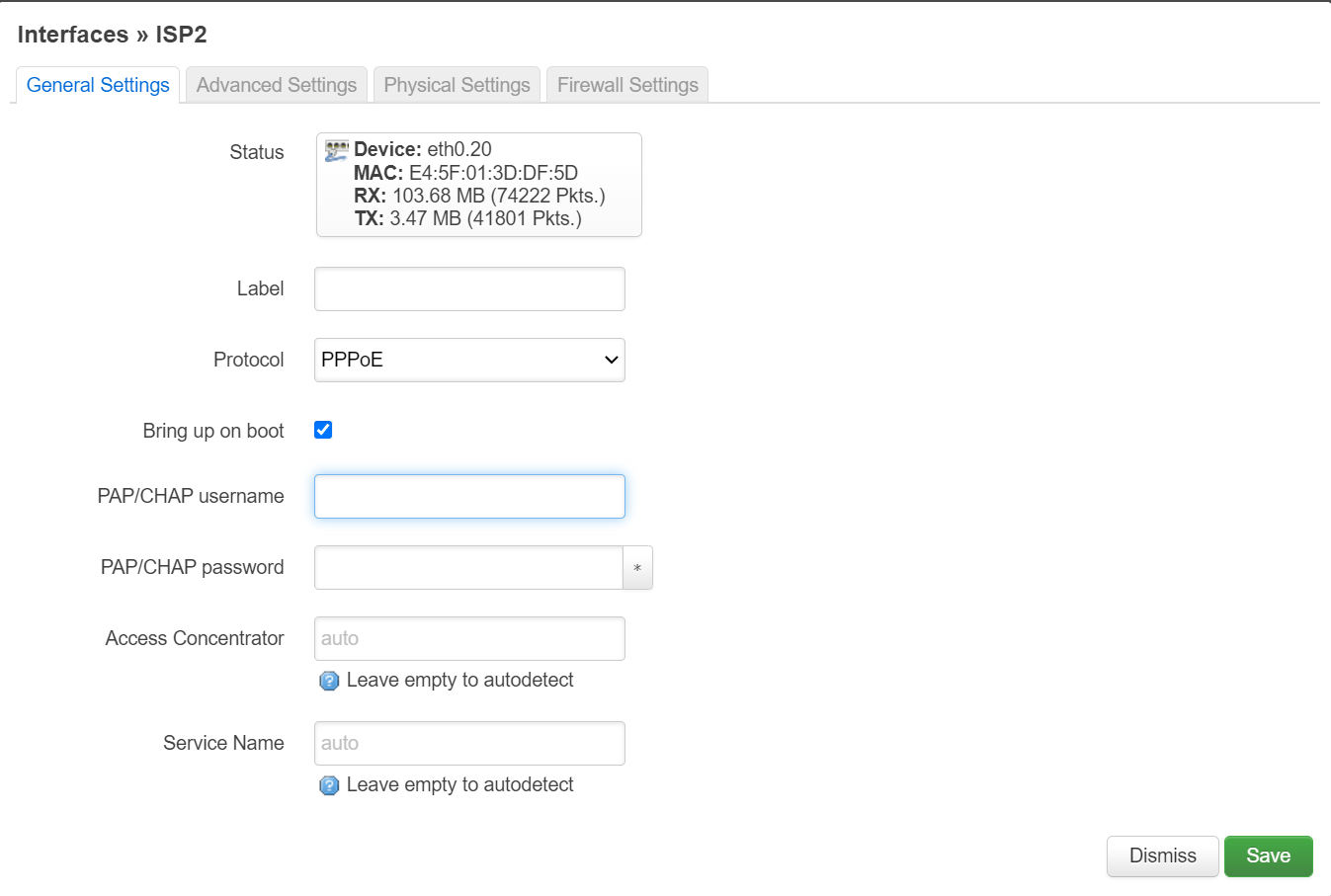
Similarly for ISP2, add another interface. For me, the protocol will be PPPoE so I selected the correct protocol and put username password. As for interface, type eth0.20. We are accessing port 2 in our switch where VLAN ID is 20. Click create/save.
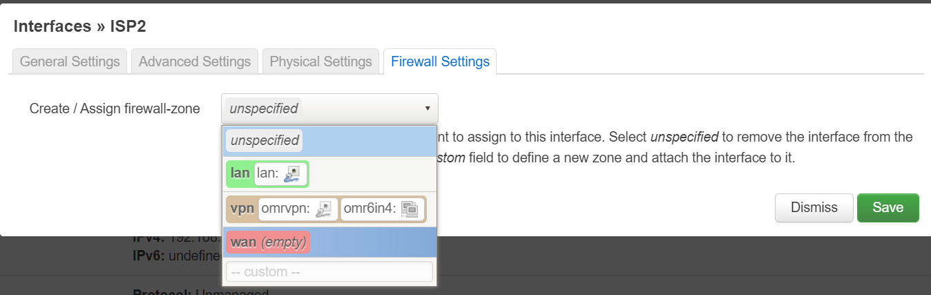
Also attach this interface to wan in firewall settings. Click save. Finally click save and apply for applying all the changes that we made.
Finally, both interfaces should up. As you can see below both got IPv4 address. All good!
part 3 – setup OpenMPTCProuter
This is our final step. In this step we will setup OpenMPTCProuter. Remember I told you to note the keys after setting up VPS? We will utilize those keys here. First go to System > OpenMPTCProuter
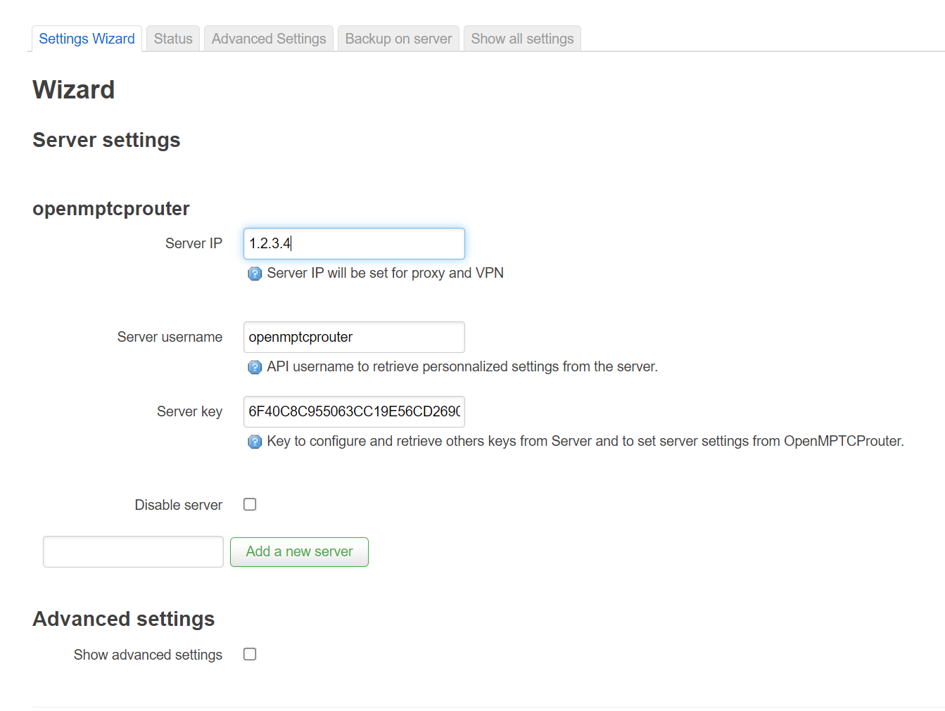
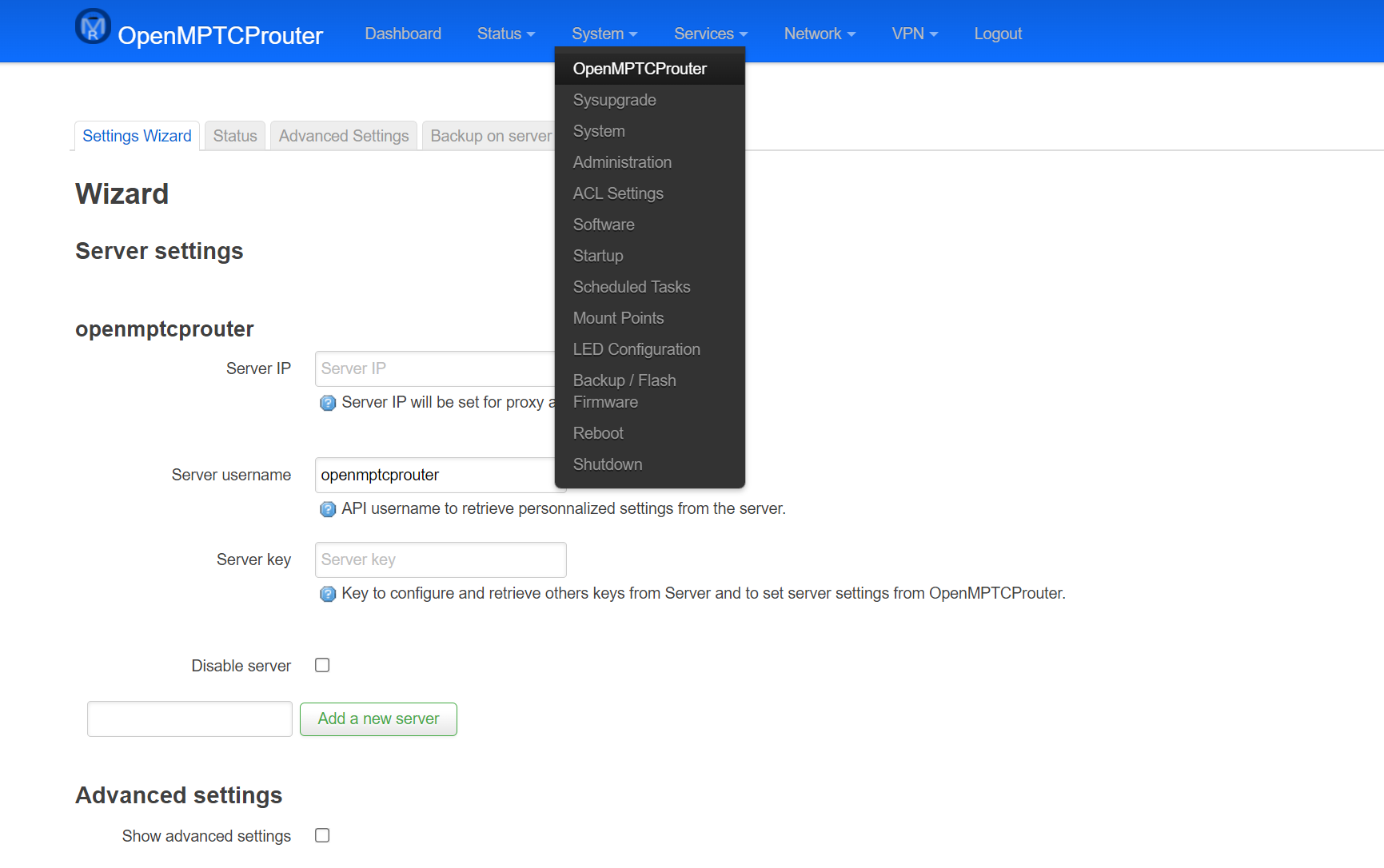 Put your server IP. Default username is openmptcprouter. Get server key from your note and paste corresponding field.
Scroll down a bit. You need to setup Multipath TCP to either master or enabled for ISP1 or ISP2. I set ISP1 as Master as it gives me stable bandwidth. I put other as Enabled.
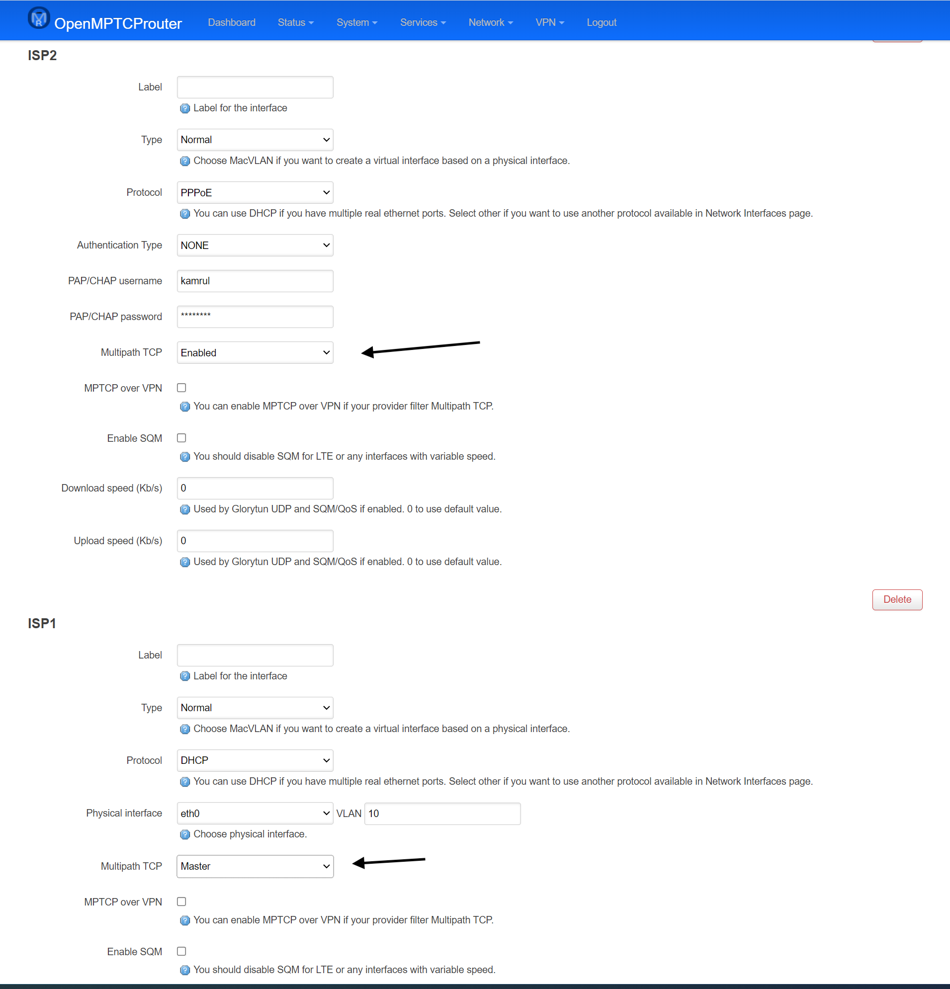
Click Save and apply from bottom.
If all goes well, you should see this screen
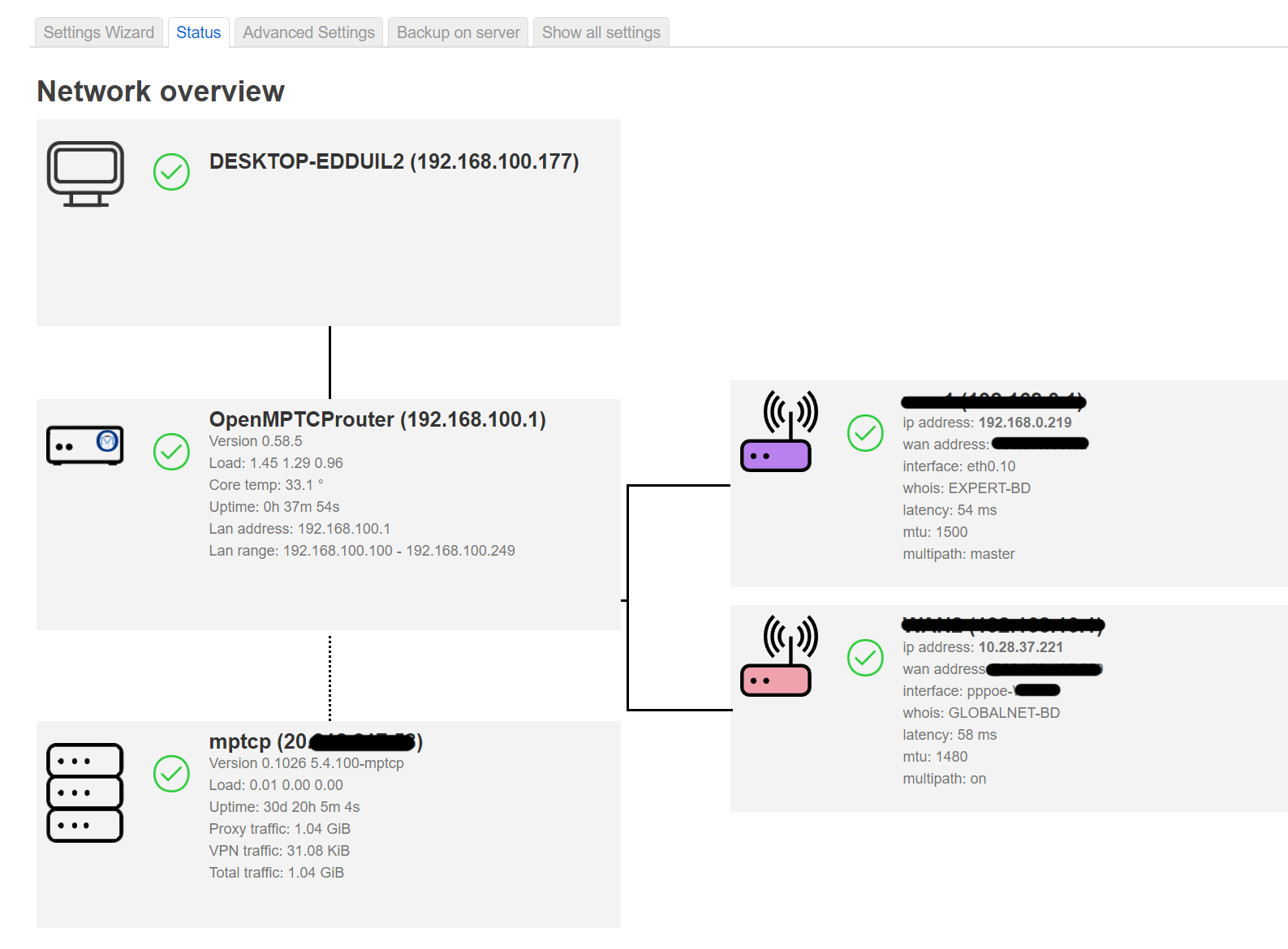
Test
Let’s test our setup. I get avg 60 Mb/s from ISP1 and 50 Mb/s from ISP2. Now I should get nearly 100+ Mb/s right? Let’s test our speed from speedtest.net
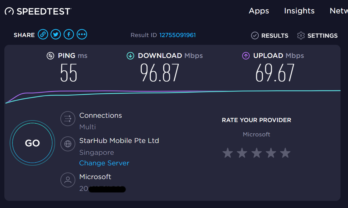
Getting nearly 100 Mb/s 😀 😀 Perfect! Let’s test download speed with IDM
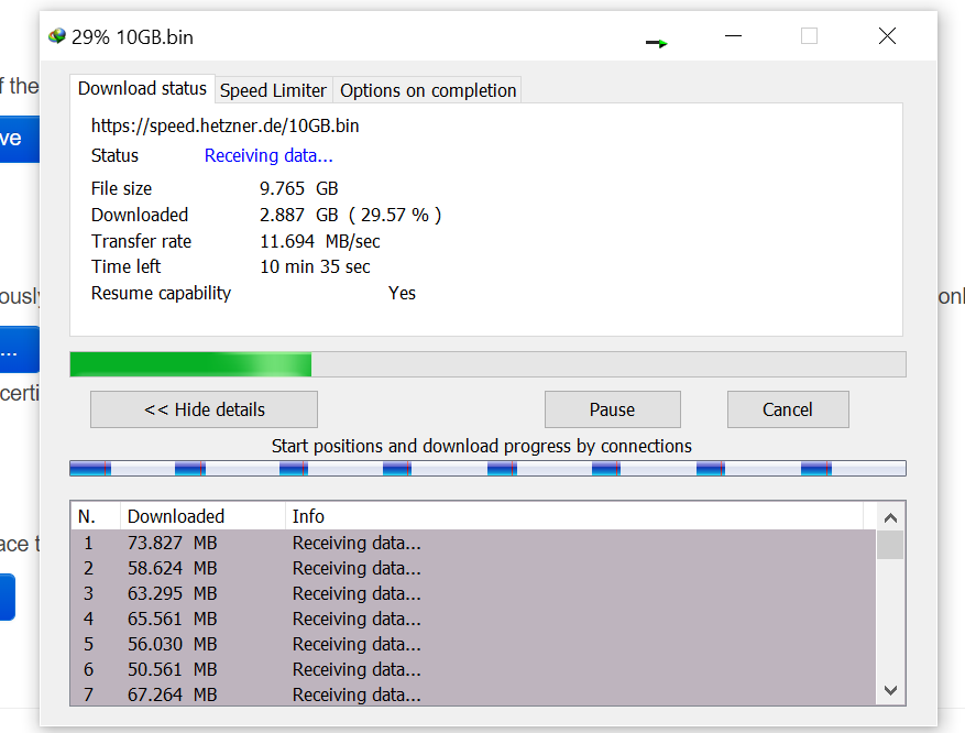 Marvellous! 😀 😀
Now you can connect your normal router/AP with switch (connect with any LAN port). Router should be in DHCP so that it can grab IP from OpenMPTCProuter device/RPI4. In that way we can share our combined internet speed to other end devices.
Profit!